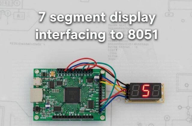
Interfacing 7-Segment Display with 8051 (AT89C52)
7 segment display with 8051
Would you like to join our comprehensive practical video course on the AT89C52 Microcontroller?
Complete Video Course on AT89C52 Microcontroller

Interfacing 7-segment display with 8051: The 7-segment display is one of the most commonly used output devices in embedded systems to represent numeric data. It consists of seven light-emitting diodes (LEDs) arranged in a figure-eight pattern, allowing digits 0–9 to be displayed. In this tutorial, you will learn how to interface a 7-segment display with the AT89C52 microcontroller, understand its internal structure, and write a simple program to display numbers using Embedded C in Keil µVision.
Understanding the 7-Segment Display
A 7-segment display contains seven LEDs named ‘a’ through ‘g’ and an optional ‘dp’ (decimal point). The display is available in two configurations:
- Common Cathode (CC): All LED cathodes are connected to ground, and individual segments are turned ON by applying logic HIGH.
- Common Anode (CA): All LED anodes are connected to +Vcc, and segments are turned ON by applying logic LOW.
In this tutorial, we use a Common Cathode type for simplicity.
Segment Identification
Each LED segment corresponds to a specific pin. By controlling the combination of ON/OFF states, we can display digits 0–9.
Segment to Display Mapping (Common Cathode):
| Digit | a | b | c | d | e | f | g | HEX Code |
|---|---|---|---|---|---|---|---|---|
| 0 | 1 | 1 | 1 | 1 | 1 | 1 | 0 | 0x3F |
| 1 | 0 | 1 | 1 | 0 | 0 | 0 | 0 | 0x06 |
| 2 | 1 | 1 | 0 | 1 | 1 | 0 | 1 | 0x5B |
| 3 | 1 | 1 | 1 | 1 | 0 | 0 | 1 | 0x4F |
| 4 | 0 | 1 | 1 | 0 | 0 | 1 | 1 | 0x66 |
| 5 | 1 | 0 | 1 | 1 | 0 | 1 | 1 | 0x6D |
| 6 | 1 | 0 | 1 | 1 | 1 | 1 | 1 | 0x7D |
| 7 | 1 | 1 | 1 | 0 | 0 | 0 | 0 | 0x07 |
| 8 | 1 | 1 | 1 | 1 | 1 | 1 | 1 | 0x7F |
| 9 | 1 | 1 | 1 | 1 | 0 | 1 | 1 | 0x6F |
Circuit Description
- Connect the 7-segment display’s segment pins (a–g) to Port 1 of AT89C52 (P1.0–P1.6).
- Connect the common cathode terminal to GND.
- Use 220Ω resistors in series with each segment to limit current.
When the microcontroller sends the binary pattern corresponding to a number, the respective segments light up to display that digit.
Example Code: Display Digits 0–9 on 7-Segment Display
#include <reg51.h>
void delay(unsigned int t)
{
    unsigned int i, j;
    for(i=0; i<t; i++)
        for(j=0; j<1275; j++);
}
void main()
{
    unsigned char code seg_code[] = {0x3F,0x06,0x5B,0x4F,0x66,0x6D,0x7D,0x07,0x7F,0x6F};
    unsigned char i;
    while(1)
    {
        for(i=0;i<10;i++)
        {
            P1 = seg_code[i];  // Send segment data to Port 1
            delay(500);        // Delay between digits
        }
    }
}Working Principle
- The seg_code[] array holds the hexadecimal values for digits 0–9.
- These values determine which LED segments are ON or OFF.
- The program sends each code to Port 1, lighting up the segments to form the corresponding digit.
- The
delay()function provides a visible transition time between numbers.
Multiplexing Multiple 7-Segment Displays
To display more than one digit, you can use multiplexing, where each display is activated sequentially for a short time.
Steps for multiplexing:
- Connect each 7-segment’s common terminal to a transistor driver.
- Connect all segment pins in parallel.
- Send segment data for the first digit and activate its transistor briefly.
- Repeat for each digit rapidly (~1ms per digit).
This gives the illusion of all digits being ON simultaneously.
Circuit Design in Proteus
In Proteus, place:
- AT89C52 microcontroller
- Common Cathode 7-segment display
- Resistors (220Ω for each segment)
Connect: - Segments a–g to Port 1 pins (P1.0–P1.6)
- Common cathode to GND
Run the simulation and observe the digits 0–9 cycling on the display.
Applications
- Digital counters
- Timers and clocks
- Numeric indicators (temperature, voltage, etc.)
- Token and score displays
Summary
The 7-segment display is a simple and effective numeric display device for embedded systems. With the AT89C52 microcontroller, you can easily control it using port outputs and hexadecimal segment codes. The same logic extends to multiple digits using multiplexing techniques for projects like clocks and counters.
Learn More
Do you want to go beyond just configuration and build real embedded projects?
🎓 Join our Complete Practical Video Course to Master the AT89C52 Microcontroller.
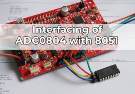
Get step-by-step guidance on Timers, Interrupts, UART, I/O Interfacing, ADC (using ADC0804), and I²C/SPI (Software Implementation) — with real circuits, simulations, and hardware demonstrations!
Complete Video Course on AT89C52 Microcontroller
Downloading and Installing Keil µVision IDE
- Visit the official Keil website at https://www.keil.com or KEIL IDE
- Navigate to the Downloads → C51 Compiler section.
- Register (if required) and download the latest version of Keil µVision for 8051 (C51).
- Run the installer and follow the on-screen instructions.
- Once installed, launch the Keil µVision IDE from the Start Menu.