ADC Module of PIC Microcontroller (PIC18F4550)
ADC in PIC microcontroller(PIC18F4550)
Full Practical Course on PIC18F4550 Microcontroller

Configuring ADC in PIC Microcontroller (Analog to Digital Converter) Module of PIC18F4550
Suppose you’ve ever wanted to measure analog signals like temperature, light intensity, or voltage using a PIC microcontroller? In that case, the ADC (Analog-to-Digital Converter) is your gateway to the real world of signal processing.
In this post, we’ll explore how to configure and use the ADC module of the PIC18F4550 with practical steps – exactly the way you’ll do it in real embedded systems projects.
By the end of this post, you’ll not only understand the ADC concept but also be able to read sensor data and display it using C code on MPLAB X IDE or Proteus simulation.
ADC in PIC (PIC18F4550)
PIC18F4550 has a 10-bit ADC (Analog to Digital Converter) which can convert analog voltages (0V to 5V) into a digital value between 0 and 1023.
This means each bit represents approximately 4.88mV (5V / 1024).
Key Features:
- 10-bit resolution
- Up to 13 analog input channels (AN0 to AN12)
- Selectable voltage reference (Vref+ / Vref−)
- Conversion speed control via ADC clock
- Result format: left or right justified
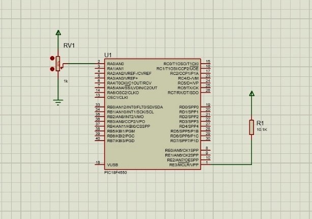
Step 1: Understanding ADC Pins
The ADC channels are multiplexed with PORTA and PORTE pins.
ADC in PIC microcontroller (PIC18F4550)
| ADC Channel | Pin | Port Pin Name |
|---|---|---|
| AN0 | 2 | RA0 |
| AN1 | 3 | RA1 |
| AN2 | 4 | RA2 |
| AN3 | 5 | RA3 |
| AN4 | 6 | RA5 |
| AN5–AN12 | Various | RE0–RE2 etc. |
So, before configuring the ADC in PIC microcontroller (PIC18F4550), make sure the corresponding pins are set as analog inputs in the ADCON1 register.
Step 2: Register Configuration Overview
To make the ADC work, we need to configure a few important registers.
| Register | Purpose |
|---|---|
ADCON0 | Turns ADC ON/OFF, selects channel, starts conversion |
ADCON1 | Sets reference voltage, configures analog/digital pins |
ADCON2 | Controls result justification, acquisition time, and conversion clock |
ADRESH:ADRESL | Stores the 10-bit result |
Step 3: Configuration Steps (with Code)
Let’s go step-by-step:
#include <xc.h>
#define _XTAL_FREQ 8000000  // 8 MHz oscillator

void ADC_Init()
{
    ADCON1 = 0x0E;     // AN0 = Analog, others Digital
    ADCON2 = 0x89;     // Right justified, 8TAD, Fosc/8
    ADCON0 = 0x01;     // Select channel AN0, ADC ON
}

unsigned int ADC_Read(unsigned char channel)
{
    ADCON0 &= 0xC5;            // Clear channel selection bits
    ADCON0 |= (channel << 3);  // Select ADC channel
    __delay_ms(2);             // Acquisition time
    GO_nDONE = 1;              // Start conversion
    while(GO_nDONE);           // Wait until conversion complete
    return ((ADRESH<<8)+ADRESL); // Return result
}

void main(void)
{
    unsigned int adc_value;
    ADC_Init();

    TRISD = 0x00; // PORTD as output (for display purpose)

    while(1)
    {
        adc_value = ADC_Read(0);   // Read from channel 0
        PORTD = adc_value >> 2;    // Simple output demo
        __delay_ms(100);
    }
}
Explanation:
ADCON1configures the pin type (analog/digital).ADCON2sets the timing and justification.ADCON0enables the ADC and selects the channel.GO_nDONEstarts and monitors conversion.- The result is fetched from
ADRESHandADRESL.
Step 4: Practical Demonstration
If you’re using:
- Proteus Simulation → Connect a variable resistor (potentiometer) to RA0.
- Hardware Board → Connect a sensor (like LM35 temperature sensor) to AN0 pin.
Run the program and observe how the PORTD LEDs or your LCD respond to varying input voltages.
✅ Tip: Add a 10nF–100nF capacitor from the analog input pin to ground and ensure proper grounding.
This hands-on test shows how the PIC18F4550 converts analog signals into meaningful digital data — a skill every embedded engineer must master.
Step 5: Going Beyond – Build a Real Project
Now that you’ve configured the ADC in PIC microcontroller (PIC18F4550) successfully, you can expand this into:
- Temperature Monitor System using LM35
- Light Intensity Meter using LDR
- Battery Voltage Indicator
Each of these projects is an exciting step toward real-world embedded design.
Ready to Master PIC18F4550 than just learning ADC in PIC microcontroller?
If you enjoyed this tutorial and want to learn the complete practical side of PIC18F4550, including:
- Timers, Interrupts, and UART Communication
- PWM for Motor Control
- USB Interface & Sensors Integration
- Real-world Project Building
👉 Then don’t miss our Premium Course: “Mastering PIC18F4550 Microcontroller”
🎓 A complete hands-on training designed for students, hobbyists, and engineers.
Learn, Code, and Build Real Embedded Systems Projects!
➡️ Start Learning Now at Master PIC18F4550 Programming
Full Practical Course on PIC18F4550 Microcontroller
Product: PIC18F4550
💬Frequently Asked Questions (FAQ)
1️⃣ What is the purpose of the ADC in PIC (PIC18F4550)?
The ADC (Analog-to-Digital Converter) allows the PIC18F4550 to read analog signals — such as from sensors like temperature, light, or voltage sensors — and convert them into digital values that the microcontroller can process.
It has a 10-bit resolution, which means it can represent an analog signal as a digital number from 0 to 1023. Each step represents approximately 4.88 mV (when using a 5V reference).
There are 13 ADC input channels — from AN0 to AN12 — which can be individually configured as analog or digital pins.
The channel is selected by setting the CHS bits (bits 5–2) of the ADCON0 register.
For example:ADCON0bits.CHS = 0; selects AN0,ADCON0bits.CHS = 1; selects AN1, and so on.
Typically, it can measure from 0V to Vref+ (usually +5V).
If you’re using external references (Vref+ and Vref−), the range adjusts accordingly.
Fluctuations may occur due to:
Electrical noise in analog lines
Missing decoupling capacitors near Vdd/Vss
Noisy power supply or long signal wires
Lack of acquisition delay before conversion
Absolutely!
For LM35: connect Vout → AN0, Vcc → +5V, GND → GND.
For LDR: use a voltage divider circuit and feed the midpoint voltage to AN0.
These are perfect beginner projects using the ADC.
No. You can choose which pins to act as analog using the ADCON1 register.
For example:ADCON1 = 0x0E; → makes AN0 analog and all others digital.
The conversion time depends on the ADC clock and acquisition time set in ADCON2.
Typically, one conversion takes about 12 TAD cycles, where TAD is the ADC clock period.
You can start with:
PIC18F4550 Development Board (available at Bitziga Store)
10kΩ Potentiometer or LM35 Sensor
MPLAB X IDE + XC8 Compiler
Proteus Simulation (optional)
You can join our premium hands-on course:
🎓 “Mastering PIC18F4550 Microcontroller” – A complete practical training covering ADC, Timers, Interrupts, UART, PWM, and real-world projects.
👉Mastering PIC18F4550 Microcontroller
Yes! This is part of our “Design to Learn” campaign.
Upcoming posts will include:
Timer Configuration and Delay Generation
UART Communication and Serial Data Display
PWM Generation and Motor Control Projects
Stay tuned and subscribe for updates 🚀