Configuring UART Module of PIC18F4550
Full Practical Course on PIC18F4550 Microcontroller

- Full Practical Course on PIC18F4550 Microcontroller
- Configuring UART Module of PIC18F4550 – Serial Communication Made Easy!
- Understanding UART in PIC18F4550
- Step-by-Step Configuration
- Circuit Diagram Description
- Testing the Code
- Practical Applications
- Next Step: Master the UART module and more
- Full Practical Course on PIC18F4550 Microcontroller
- 💬Frequently Asked Questions (FAQ)
Configuring UART Module of PIC18F4550 – Serial Communication Made Easy!
The UART (Universal Asynchronous Receiver Transmitter) module in the PIC18F4550 microcontroller is one of the most essential peripherals for embedded engineers. It enables serial communication between your microcontroller and external devices like PCs, GSM modules, GPS receivers, Bluetooth modules, and more.
In this blog, we’ll take you through the practical steps to configure and use the UART module on the PIC18F4550 using the MPLAB X IDE and XC8 compiler – the same way engineers do it in real projects.
Goal: By the end of this post, you’ll be able to send and receive data via UART and interface your PIC18F4550 with a PC using a USB-to-Serial converter.
Understanding UART in PIC18F4550
UART provides full-duplex serial communication using two pins:
| Signal | Pin | Description |
|---|---|---|
| TX (Transmit) | RC6 | Sends data serially |
| RX (Receive) | RC7 | Receives data serially |
Baud Rate:
You can set the communication speed (baud rate) by configuring the SPBRG and SPBRGH registers. Common baud rates are 9600 bps, 19200 bps, etc.
Important Registers
| Register | Purpose |
|---|---|
| TXSTA | Transmit Status and Control |
| RCSTA | Receive Status and Control |
| SPBRG / SPBRGH | Baud Rate Generator |
| PIR1, PIE1 | Interrupt and flag bits for TX/RX |
Step-by-Step Configuration
1️⃣ Configure UART Pins
Let’s go step-by-step:
Make RC6 (TX) as output and RC7 (RX) as input.
TRISC6 = 0;  // TX as output
TRISC7 = 1; // RX as input2️⃣ Set the Baud Rate
For example, 9600 bps at 8 MHz:
SPBRG = 51;       // Baud rate value for 9600 bps
TXSTAbits.BRGH = 1; // High speed3️⃣ Enable UART Transmit and Receive
RCSTAbits.SPEN = 1;   // Enable Serial Port
TXSTAbits.TXEN = 1;   // Enable Transmission
RCSTAbits.CREN = 1; // Enable Continuous Reception4️⃣ Create Transmit and Receive Functions
void UART_TxChar(char ch) {
    while(!TXSTAbits.TRMT);  // Wait until buffer is empty
    TXREG = ch;
}

char UART_RxChar(void) {
    while(!PIR1bits.RCIF);   // Wait until data is received
    return RCREG;
}5️⃣ Transmit a String
void UART_TxString(const char *str) {
    while(*str) UART_TxChar(*str++);
}6️⃣ Example Main Program
#include <xc.h>
#define _XTAL_FREQ 8000000

void UART_Init(void);
void UART_TxChar(char);
char UART_RxChar(void);
void UART_TxString(const char *);

void main(void) {
    UART_Init();
    UART_TxString("UART Initialized!\r\n");

    while(1) {
        char data = UART_RxChar();
        UART_TxChar(data);  // Echo back received data
    }
}

void UART_Init(void) {
    TRISC6 = 0; TRISC7 = 1;
    SPBRG = 51; TXSTAbits.BRGH = 1;
    RCSTAbits.SPEN = 1;
    TXSTAbits.TXEN = 1;
    RCSTAbits.CREN = 1;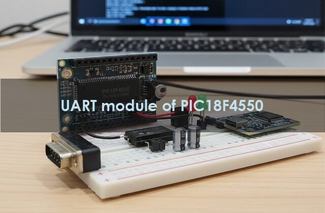
}Circuit Diagram Description
- PIC18F4550 connected to a USB-to-Serial (FT232 / CH340) converter.
- RC6 (TX) → RX of converter
- RC7 (RX) → TX of converter
- Common GND between PIC and converter
- Connect converter’s USB to PC and open any serial terminal (like PuTTY or Tera Term).
Testing the Code
- Program your PIC18F4550 with the above code.
- Open your serial terminal on PC at 9600 bps.
- Type any character — you’ll see it echoed back!
- Congratulations 🎉! You’ve successfully configured the UART.
Practical Applications
- Sending debug messages to PC
- Interfacing GSM/GPS/Bluetooth modules
- Data logging and serial monitoring
Next Step: Master the UART module and more
Want to go beyond this simple example?
Learn interrupt-driven UART, multi-device serial networks, and real-time project integration in our Full Practical Course on PIC18F4550 Microcontroller.
If you enjoyed this tutorial and want to learn the complete practicals of PIC18F4550, including:
- Timers, Interrupts, and UART Communication
- PWM for Motor Control
- USB Interface & Sensors Integration
- Real-world Project Building
👉 Then don’t miss our Premium Course: “Mastering PIC18F4550 Microcontroller”
🎓 A complete hands-on training designed for students, hobbyists, and engineers.
Learn, Code, and Build Real Embedded Systems Projects!
🎯 Hands-On | Project-Based | Engineer-Focused
Full Practical Course on PIC18F4550 Microcontroller
💬Frequently Asked Questions (FAQ)
You can start with:
PIC18F4550 Development Board (available at Bitziga Store)
10kΩ Potentiometer or LM35 Sensor
MPLAB X IDE + XC8 Compiler
Proteus Simulation (optional)
You can join our premium hands-on course:
🎓 “Mastering PIC18F4550 Microcontroller” – A complete practical training covering ADC, Timers, Interrupts, UART, PWM, and real-world projects.
👉Mastering PIC18F4550 Microcontroller
Yes! This is part of our “Design to Learn” campaign.
Upcoming posts will include:
Timer Configuration and Delay Generation
UART Communication and Serial Data Display
PWM Generation and Motor Control Projects
Stay tuned and subscribe for updates 🚀