Configuring Interrupt of PIC18F4550
- Complete Video Course on PIC18F4550 Microcontroller
- Configuring Interrupt Module of PIC18F4550 – Step-by-Step Practical Guide
- What is an Interrupt?
- Types of Interrupts in PIC18F4550
- Example: External Interrupt on INT0 (RB0 Pin)
- Explanation
- Other Common Interrupts in PIC18F4550
- Practical Applications
- Ready to learn interrupts in real projects using PIC18F4550?
- Complete Video Course on PIC18F4550 Microcontroller
- Frequently Asked Questions (FAQ)
Complete Video Course on PIC18F4550 Microcontroller

Configuring Interrupt Module of PIC18F4550 – Step-by-Step Practical Guide
Interrupts are one of the most powerful features of microcontrollers – they allow your system to respond immediately to important events like a button press, timer overflow, or received data, without continuously polling for changes. In this post, you’ll learn how to configure and handle an interrupt in PIC18F4550 microcontroller using MPLAB X IDE and the XC8 compiler through a simple LED blinking on an external interrupt example.
Goal: By the end, you’ll know how to enable, configure, and write ISR (Interrupt Service Routine) functions that make your embedded systems more responsive and efficient.
What is an Interrupt?
An interrupt is a signal that temporarily stops the normal execution of your main program to run a special function called the Interrupt Service Routine (ISR).
For example, if your PIC is busy running code and a button connected to an external interrupt pin is pressed — the microcontroller pauses the main loop, executes the ISR, and then resumes normal operation.
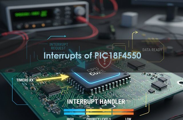
Types of Interrupts in PIC18F4550
The PIC18F4550 supports:
- External Interrupts (INT0, INT1, INT2)
- Peripheral Interrupts (like UART, ADC, Timer, CCP, etc.)
- Timer Interrupts
- USB and Special Event Triggers
Each interrupt has:
- Enable bit – turns it ON/OFF
- Flag bit – indicates if it occurred
- Priority bit – decides high or low priority
Example: External Interrupt on INT0 (RB0 Pin)
1️⃣ Circuit Description
- Connect a push button to RB0 (INT0) pin.
- Connect an LED to PORTD (RD0) with a 330Ω resistor.
- When the button is pressed → the LED toggles using an interrupt.
#include <xc.h>
#define _XTAL_FREQ 8000000

void __interrupt() ISR(void) {
    if (INT0IF) {          // Check if INT0 caused interrupt
        LATDbits.LATD0 = !LATDbits.LATD0;  // Toggle LED
        INT0IF = 0;        // Clear interrupt flag
    }
}

void main(void) {
    TRISBbits.TRISB0 = 1;  // RB0 as input (button)
    TRISDbits.TRISD0 = 0;  // RD0 as output (LED)
    LATDbits.LATD0 = 0;

    INT0IF = 0;   // Clear flag
    INT0IE = 1;   // Enable external interrupt INT0
    GIE = 1;      // Global interrupt enable

    while(1) {
        // Main loop can do other tasks
    }
}Circuit Diagram Description
VCC (5V) and GND → common reference.
Button → connected to RB0 (INT0) with a pull-down resistor.
LED → connected to RD0 via 330Ω resistor.
Explanation
- When the button is pressed, RB0 changes state → INT0 flag is set.
- MCU automatically jumps to the ISR.
- LED toggles and flag clears.
- MCU returns to the main loop — all automatically handled by hardware.
Other Common Interrupts in PIC18F4550
| Interrupt Type | Pin/Module | Typical Use |
|---|---|---|
| INT0 / INT1 / INT2 | RB0 / RB1 / RB2 | External triggers |
| TMR0 / TMR1 / TMR2 | Timer modules | Delays, periodic tasks |
| ADC | Analog Conversion Complete | Sensor reading |
| USART | Serial Receive/Transmit | UART communication |
| CCP | Capture/Compare/PWM | Signal control |
Practical Applications
- Detect button presses or sensor triggers
- Implement real-time event handling
- Perform multitasking without RTOS
- Efficient energy management in low-power devices
Ready to learn interrupts in real projects using PIC18F4550?
If you enjoyed this tutorial and want to learn the complete practical side of PIC18F4550, including:
- Timers, Interrupts, and UART Communication
- PWM for Motor Control
- USB Interface & Sensors Integration
- Real-world Project Building
👉 Then don’t miss our Premium Course: “Mastering PIC18F4550 Microcontroller”
🎓 A complete hands-on training designed for students, hobbyists, and engineers.
Learn, Code, and Build Real Embedded Systems Projects!
dsdas
➡️ Start Learning Now at Master PIC18F4550 Programming
Complete Video Course on PIC18F4550 Microcontroller
Software development tools & documents:
Frequently Asked Questions (FAQ)
PIC18F4550 supports interrupt priorities — the high-priority ISR executes first.
They temporarily pause it, execute ISR, and then resume — without losing data.
Three: INT0 (RB0), INT1 (RB1), and INT2 (RB2).
Yes, by clearing the GIE (Global Interrupt Enable) bit.
You can start with:
PIC18F4550 Development Board (available at Bitziga Store)
10kΩ Potentiometer or LM35 Sensor
MPLAB X IDE + XC8 Compiler
Proteus Simulation (optional)
You can join our premium hands-on course:
🎓 “Mastering PIC18F4550 Microcontroller” – A complete practical training covering ADC, Timers, Interrupts, UART, PWM, and real-world projects.
👉Mastering PIC18F4550 Microcontroller
Yes! This is part of our “Design to Learn” campaign.
Upcoming posts will include:
Timer Configuration and Delay Generation
UART Communication and Serial Data Display
PWM Generation and Motor Control Projects
Stay tuned and subscribe for updates 🚀