


SPI in PIC microcontroller – PIC18F4550
Complete Video Course on PIC18F4550 Microcontroller

SPI in PIC (SPI Module of PIC18F4550 – a practical guide)
The Serial Peripheral Interface (SPI) is one of the fastest and most commonly used communication protocols in embedded systems. With just four lines, SPI in PIC (PIC18F4550) enables high-speed, full-duplex communication between the PIC18F4550 microcontroller and devices like sensors, displays, memory chips, and DACs.
In this blog, we’ll walk through configuring the SPI module of the PIC18F4550, understanding master-slave roles, and creating a simple project example
🎯 Goal: After reading this post, you’ll be able to set up I/O pins, blink LEDs, and read switch states — the essential first step to mastering embedded systems.
What is SPI Communication?
SPI (Serial Peripheral Interface) is a synchronous serial communication protocol designed for short-distance, high-speed data transfer between a master and one or more slave devices.
It uses the following lines:
SS (Slave Select) – Enables specific slave device
SCK (Serial Clock) – Clock signal generated by the master
SDI (Serial Data In) – Data line for receiving
SDO (Serial Data Out) – Data line for transmitting
SPI Pins in PIC18F4550
The SPI module in PIC18F4550 is implemented through the MSSP (Master Synchronous Serial Port) peripheral.
| Signal | Pin | Function |
|---|---|---|
| SCK | RC3 (Pin 18) | Serial Clock |
| SDO | RC5 (Pin 24) | Serial Data Out |
| SDI | RC4 (Pin 23) | Serial Data In |
| SS | RA5 (Pin 7) | Slave Select |
Step 1: Configuring SPI as Master
We’ll configure the MSSP module to operate as the SPI Master, enabling it to communicate with an external SPI device, such as an EEPROM or DAC.
Code Example (MPLAB X + XC8):
#include <xc.h>

#define _XTAL_FREQ 8000000

void SPI_Init_Master(void)
{
    TRISC3 = 0;  // SCK as output
    TRISC4 = 1;  // SDI as input
    TRISC5 = 0;  // SDO as output
    TRISA5 = 0;  // SS as output

    SSPSTAT = 0x40;    // Transmit data on rising edge
    SSPCON1 = 0x21;    // Enable SPI, Master mode, Fosc/16
}

void SPI_Write(unsigned char data)
{
    SSPBUF = data;
    while(!BF);         // Wait until transmission complete
}

unsigned char SPI_Read(void)
{
    SSPBUF = 0x00;      // Send dummy data
    while(!BF);
    return SSPBUF;
}Step 2: Circuit Diagram
To visualize the setup, connect the PIC18F4550 as Master to an SPI Slave device like a 25LC256 EEPROM or MCP4921 DAC.
Connections:
- RC3 (SCK) → Slave SCK
- RC5 (SDO) → Slave SDI
- RC4 (SDI) → Slave SDO
- RA5 (SS) → Slave CS
- GND ↔ GND, VCC ↔ VCC
Would you like me to generate a SPI circuit diagram image (PIC18F4550 + 25LC256 EEPROM with all lines labeled)? I can prepare it next.
🔹 Step 3: Data Transmission Example
Example: Writing a byte (0x55) to an EEPROM.
PORTAbits.RA5 = 0;      // Select Slave
SPI_Write(0x55);        // Send data
PORTAbits.RA5 = 1; // Deselect SlaveStep 4: Testing SPI
You can test the SPI communication by reading the data back from the slave or by observing waveforms on an oscilloscope.
Real-World Applications
- Interfacing EEPROMs (25LC256, AT25 series)
- DACs and ADCs
- TFT displays (ILI9341, ST7735)
- Wireless modules (NRF24L01, RF Transceivers)
Learn More
Are you excited to build projects like SPI-based EEPROM storage, digital potentiometers, and display drivers?
🎓 Join our Full Practical Video Course on PIC18F4550 Microcontroller
Learn every module — GPIO, ADC, UART, SPI, I²C, PWM, and Interrupts — with hands-on coding and real circuit demonstrations.
➡️ Start Learning Now at “Master PIC18F4550 Programming“
Complete Video Course on PIC18F4550 Microcontroller
Software development tools & documents:
Tags: SPI in PIC (SPI Module of PIC18F4550), Serial Peripheral Interface
💬Frequently Asked Questions (FAQ)
The SPI (Serial Peripheral Interface) module in the PIC18F4550 microcontroller is used for high-speed, synchronous serial communication between the microcontroller and peripheral devices like EEPROMs, sensors, and DACs. It allows full-duplex data transfer using four main lines: SCK, SDI, SDO, and SS.
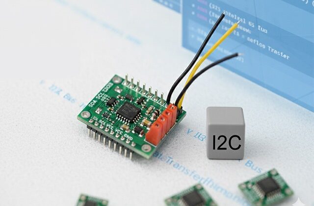
SPI uses separate data lines for transmission (SDO) and reception (SDI), allowing full-duplex communication, while I2C uses a single bidirectional data line (SDA) and requires addressing for multiple devices. SPI is faster but uses more pins than I2C.
The SPI module in the PIC18F4550 can operate up to Fosc/4 in master mode, allowing data transfer speeds depending on the system clock frequency. For example, with a 20 MHz clock, SPI can run at 5 MHz.
Yes, the SPI in PIC (SPI module in PIC18F4550) can be configured to work as either a master or a slave device by setting the appropriate bits in the SSPCON1 register.
The main registers for SPI configuration include SSPCON1, SSPSTAT, and SSPBUF. These control SPI mode selection, clock polarity/phase, and data buffering during transmission and reception.
The SS (Slave Select) pin is used to enable or disable communication with a specific SPI slave device. When the SS pin is low, the corresponding slave is selected and ready to communicate; when high, it ignores SPI signals.
You can simulate SPI communication in Proteus by connecting the PIC18F4550 to an SPI peripheral like a 25LC256 EEPROM, ensuring proper connections (SCK, SDO, SDI, SS), and observing data transfer using virtual terminal or logic analyzer tools.
Yes, multiple SPI devices can share the same SCK, SDI, and SDO lines, but each device must have its own SS (Slave Select) line controlled by the microcontroller to avoid conflicts.
You can join our premium hands-on course:
🎓 “Mastering PIC18F4550 Microcontroller” – A complete practical training covering ADC, Timers, Interrupts, UART, PWM, and real-world projects.
👉Mastering PIC18F4550 Microcontroller
Yes! This is part of our “Design to Learn” campaign.
Upcoming posts will include:
Timer Configuration and Delay Generation
UART Communication and Serial Data Display
PWM Generation and Motor Control Projects
Stay tuned and subscribe for updates 🚀


Looking forward for the video tutorials. 🙂