UART in 8051 Microcontroller (AT89C52)
UART in 8051
- Complete Video Course on AT89C52 Microcontroller
- Introduction
- Registers Used in Serial Communication
- SCON (Serial Control Register)
- TMOD (Timer Mode Control Register)
- TH1 (Timer 1 High Byte Register)
- PCON (Power Control Register)
- Serial Communication Modes
- Baud Rate Calculation
- Explanation of the Code
- Common Applications of UART in AT89C52
- Summary
- Upcoming AT89C52 programming tutorials, including peripheral interfacing and project development.
- Learn More
- Complete Video Course on AT89C52 Microcontroller
- 💬Frequently Asked Questions (FAQ)
Would you like to join our comprehensive practical video course on the AT89C52 Microcontroller?
Complete Video Course on AT89C52 Microcontroller

Introduction
UART in 8051: Serial communication allows the microcontroller to exchange data with external devices such as computers, Bluetooth modules, GSM modems, and other microcontrollers. The AT89C52 microcontroller includes a built-in UART (Universal Asynchronous Receiver and Transmitter) module for full-duplex serial communication. This tutorial explains how UART works in AT89C52 and how to configure it using registers and embedded C code.
Prerequisites
Before reading this blog, make sure you are familiar with how to install the Keil µVision IDE, create a new project, and compile the code successfully.
If you haven’t done this yet, check out our detailed guide:
Getting Started with Keil IDE for AT89C52 Microcontroller
Basics of Serial Communication
In serial communication, data is transmitted one bit at a time through a single line, making it more efficient for long-distance transmission than parallel communication.
There are two main types of serial communication:
- Synchronous: Sender and receiver share a common clock signal.
- Asynchronous: No clock is shared; both ends agree on the same baud rate.
The AT89C52 UART operates in asynchronous mode by default.
UART Features in AT89C52
- Full-duplex communication (simultaneous transmit and receive)
- Configurable baud rate
- 1 Start bit, 8 Data bits, 1 Stop bit format
- Interrupt-driven or polling mode operation
- Baud rate generation using Timer 1 or Timer 2
UART Pins
| Pin | Port | Description |
|---|---|---|
| TXD | P3.1 | Transmit data (output) |
| RXD | P3.0 | Receive data (input) |
These two pins are connected internally to the serial communication hardware module of AT89C52.
Registers Used in Serial Communication
SCON (Serial Control Register)
Controls serial port operation and mode selection.
Address: 98H
SCON Register Bit Format:
| Bit | 7 | 6 | 5 | 4 | 3 | 2 | 1 | 0 |
|---|
| Symbol | SM0 | SM1 | SM2 | REN | TB8 | RB8 | TI | RI |
| Function | Serial mode bit 0 | Serial mode bit 1 | Multiprocessor communication enable | Receive enable | Transmit bit 8 (for 9-bit mode) | Receive bit 8 (for 9-bit mode) | Transmit interrupt flag | Receive interrupt flag |
Common Setting for Mode 1 (8-bit UART):
SCON = 0x50; → SM0=0, SM1=1 (Mode 1), REN=1, others=0 |
TMOD (Timer Mode Control Register)
Used to configure Timer 1 in Mode 2 (Auto-reload) to generate the baud rate.
TMOD Register Bit Format:
| Bit | 7 | 6 | 5 | 4 | 3 | 2 | 1 | 0 |
|---|
| Function | GATE1 | C/T1 | M1_1 | M0_1 | GATE0 | C/T0 | M1_0 | M0_0 |
TH1 (Timer 1 High Byte Register)
Holds reload value to generate the desired baud rate.
Example: For 9600 bps at 11.0592 MHz → TH1 = 0xFD
PCON (Power Control Register)
Controls power management and serial baud rate doubling.
Address: 87H
Key Bit:
- SMOD (Bit 7): Doubles the baud rate when set to 1.
Example:PCON |= 0x80;→ Enables SMOD = 1
Serial Communication Modes
AT89C52 supports four serial communication modes via the SCON register:
| Mode | Bits | Function | Baud Rate |
|---|---|---|---|
| 0 | 8-bit shift register | Synchronous mode | fosc / 12 |
| 1 | 10-bit UART | 1 start + 8 data + 1 stop | Variable |
| 2 | 11-bit UART (fixed baud rate) | 1 start + 8 data + 1 stop + 9th bit | fosc / 64 or fosc / 32 |
| 3 | 11-bit UART (variable baud rate) | Same as Mode 2 | Variable |
Most applications use Mode 1 for standard UART communication.
Baud Rate Calculation
Baud rate in Modes 1 and 3 is derived from Timer1 overflow rate.
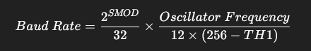
Example: For 11.0592 MHz crystal, the desired baud rate = 9600 bps
Substituting values,

Value to be loaded to the register, TH1 = 0xFD
Example: For 11.0592 MHz crystal, desired baud rate = 9600 bps
Substituting values,
UART in 8051
#include <REGX52.H>

void UART_Init(void)
{
  TMOD = 0x20;     // Timer1 Mode2
  TH1  = 0xFD;     // Baud rate 9600
  SCON = 0x50;     // 8-bit UART, enable receiver
  TR1  = 1;        // Start Timer1
}

void UART_TxChar(char ch)
{
  SBUF = ch;       // Load data to transmit buffer
  while(TI == 0);  // Wait for transmission to complete
  TI = 0;          // Clear transmit flag
}

char UART_RxChar(void)
{
  while(RI == 0);  // Wait for reception
  RI = 0;          // Clear receive flag
  return SBUF;     // Return received character
}

void main(void)
{
  char data;
  UART_Init();
  while(1)
  {
    UART_TxChar('H');
    UART_TxChar('i');
    UART_TxChar('\n');
    data = UART_RxChar();  // Echo received data
    UART_TxChar(data);
  }
}Explanation of the Code
- Timer1 is used to generate the baud rate.
SBUFregister holds transmitted or received data.TIandRIFlags indicate completion of transmit and receive, respectively.- The program continuously sends “Hi” and echoes received data.
Common Applications of UART in AT89C52
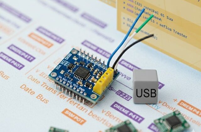
- Serial communication with PC through USB-to-UART converter
- Interfacing Bluetooth (HC-05/HC-06) modules
- GSM or GPS module interfacing
- Communication between two microcontrollers
Summary
Serial communication (UART) is one of the most useful features of the AT89C52 microcontroller. It enables data exchange between the MCU and external devices efficiently. By configuring SCON, TMOD, and TH1 registers correctly, reliable full-duplex serial communication can be achieved at standard baud rates like 9600 or 19200 bps.
Upcoming AT89C52 programming tutorials, including peripheral interfacing and project development.
Learn More
Do you want to go beyond just configuration and build real embedded projects?
🎓 Join our Complete Practical Video Course to Master the AT89C52 Microcontroller.
Get step-by-step guidance on Timers, Interrupts, UART, I/O Interfacing, ADC (using ADC0804), and I²C/SPI (Software Implementation) — with real circuits, simulations, and hardware demonstrations!
Complete Video Course on AT89C52 Microcontroller
Downloading and Installing Keil µVision IDE
- Visit the official Keil website at https://www.keil.com or KEIL IDE
- Navigate to the Downloads → C51 Compiler section.
- Register (if required) and download the latest version of Keil µVision for 8051 (C51).
- Run the installer and follow the on-screen instructions.
- Once installed, launch the Keil µVision IDE from the Start Menu.
# UART in 8051#KEIL #Keil IDE for programming 8051 #UART # AT89C52