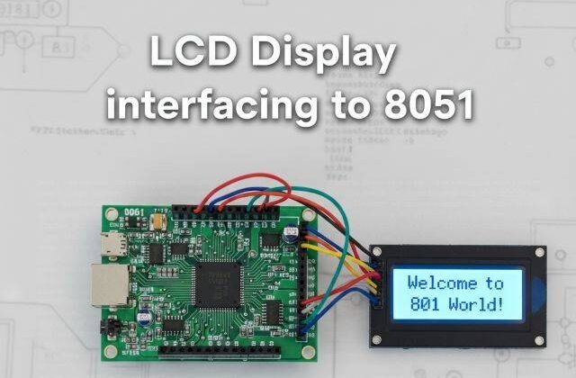
Interfacing LCD Display with 8051 (AT89C52)
LCD interfacing with 8051
Would you like to join our comprehensive practical video course on the AT89C52 Microcontroller?
Complete Video Course on AT89C52 Microcontroller

Introduction
LCD interfacing with 8051: The 16×2 LCD (Liquid Crystal Display) is one of the most widely used display modules in embedded systems. It allows displaying alphanumeric characters, messages, and variable data such as sensor readings. In this tutorial, we will learn how to interface a 16×2 LCD with the AT89C52 microcontroller, configure its control pins, send commands/data, and display text using Embedded C in Keil µVision.
Understanding the 16×2 LCD Module
A 16×2 LCD can display 16 characters per line on two lines, with each character made up of a 5×8 dot matrix. The module operates in either 8-bit mode or 4-bit mode. Here, we use the 8-bit mode for simplicity.
The LCD has two main registers:
- Command Register: Stores instructions such as clearing the display, cursor positioning, and display control.
- Data Register: Holds the data (ASCII value) to be displayed on the screen.
Pin Configuration of 16×2 LCD
| Pin No | Symbol | Function | Connection |
|---|---|---|---|
| 1 | VSS | Ground | GND |
| 2 | VCC | Supply voltage | +5V |
| 3 | VEE | Contrast adjustment | Connected to 10kΩ potentiometer |
| 4 | RS | Register Select (0=Command, 1=Data) | P2.0 |
| 5 | RW | Read/Write (0=Write, 1=Read) | GND (Write mode) |
| 6 | EN | Enable (Triggers data read/write) | P2.1 |
| 7–14 | D0–D7 | Data lines | P1.0–P1.7 |
| 15 | LED+ | Backlight | +5V |
| 16 | LED- | Backlight GND | GND |
LCD Commands (Common Instructions)
| Command (Hex) | Description |
|---|---|
| 0x01 | Clear display |
| 0x02 | Return cursor to home position |
| 0x06 | Increment cursor |
| 0x0C | Display ON, Cursor OFF |
| 0x38 | 8-bit, 2-line, 5×8 dots |
| 0x80 | Move cursor to first line |
| 0xC0 | Move cursor to second line |
Circuit Description
- Connect LCD data pins D0–D7 to Port 1 of AT89C52.
- Connect RS → P2.0, EN → P2.1, and RW → GND.
- Use a 10kΩ potentiometer across VEE to adjust contrast.
- Connect VSS → GND, VCC → +5V, and backlight pins (15, 16) to +5V and GND respectively.
Example Code: Display Text on LCD using AT89C52
LCD interfacing with 8051
#include <reg51.h>
#define lcd_port P1
sbit rs = P2^0;
sbit en = P2^1;

void lcd_cmd(unsigned char cmd)
{
    lcd_port = cmd;
    rs = 0;          // Command mode
    en = 1;
    en = 0;
}

void lcd_data(unsigned char dat)
{
    lcd_port = dat;
    rs = 1;          // Data mode
    en = 1;
    en = 0;
}

void delay(unsigned int t)
{
    unsigned int i, j;
    for(i=0;i<t;i++)
        for(j=0;j<1275;j++);
}

void lcd_init()
{
    lcd_cmd(0x38);   // 8-bit, 2 lines
    lcd_cmd(0x0C);   // Display ON, Cursor OFF
    lcd_cmd(0x06);   // Increment cursor
    lcd_cmd(0x01);   // Clear display
    lcd_cmd(0x80);   // Move cursor to first line
}

void lcd_string(char *str)
{
    while(*str)
    {
        lcd_data(*str++);
        delay(2);
    }
}

void main()
{
    lcd_init();
    lcd_string("Bitziga Tech");
    lcd_cmd(0xC0);   // Move to 2nd line
    lcd_string("AT89C52 LCD Demo");
    while(1);
}
Working Explanation
- The function lcd_cmd() sends instructions to the command register (e.g., clear display).
- The lcd_data() function sends ASCII characters to the display.
- RS selects between command/data, EN triggers data transfer.
- lcd_init() initializes LCD parameters before writing text.
- The message “Bitziga Tech” appears on the first line and “AT89C52 LCD Demo” on the second.
Circuit Design in Proteus
In Proteus, place:
- AT89C52 Microcontroller
- 16×2 LCD module
- 10kΩ potentiometer for contrast
- Power supply (5V) and ground connections
Connect as per the circuit description.
Run the simulation; the LCD will display both lines of text sequentially.
Applications
- Displaying sensor data (temperature, humidity, voltage, etc.)
- Menu-based embedded systems
- Digital meters and counters
- User interfaces in embedded devices
Summary
Interfacing a 16×2 LCD with the AT89C52 microcontroller is a simple yet essential experiment for beginners. It demonstrates how data and command registers work in peripheral communication. Understanding this concept is crucial for developing real-world embedded projects requiring text or numeric display.
Learn More
Do you want to go beyond just configuration and build real embedded projects?
🎓 Join our Complete Practical Video Course to Master the AT89C52 Microcontroller.
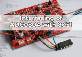
Get step-by-step guidance on Timers, Interrupts, UART, I/O Interfacing, ADC (using ADC0804), and I²C/SPI (Software Implementation) — with real circuits, simulations, and hardware demonstrations!
Complete Video Course on AT89C52 Microcontroller
Downloading and Installing Keil µVision IDE
- Visit the official Keil website at https://www.keil.com or KEIL IDE
- Navigate to the Downloads → C51 Compiler section.
- Register (if required) and download the latest version of Keil µVision for 8051 (C51).
- Run the installer and follow the on-screen instructions.
- Once installed, launch the Keil µVision IDE from the Start Menu.