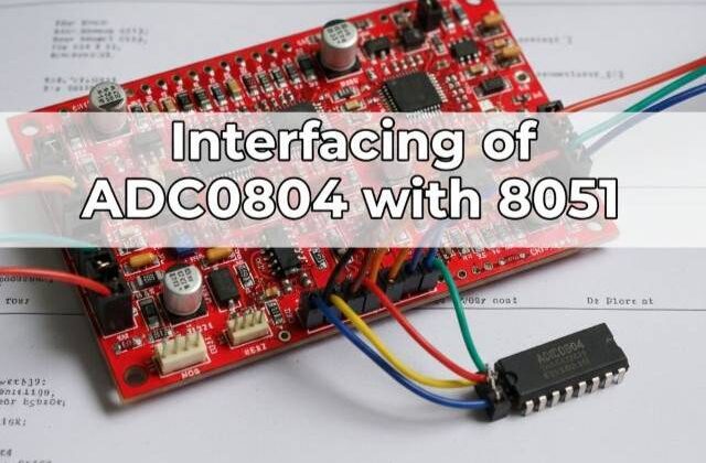
ADC0804 Interfacing with 8051 (AT89C52)
ADC0804 Interfacing with 8051
Would you like to join our comprehensive practical video course on the AT89C52 Microcontroller?
Complete Video Course on AT89C52 Microcontroller

Introduction
ADC0804 Interfacing with 8051: The AT89C52 microcontroller is purely digital in nature and cannot directly read analog signals. However, many sensors and real-world devices generate analog outputs (such as temperature, voltage, and light intensity). To process these signals, we need an Analog-to-Digital Converter (ADC). The ADC0804 is an 8-bit ADC IC commonly used with 8051 microcontrollers for converting analog voltages into digital values. In this tutorial, you’ll learn how to interface the ADC0804 with AT89C52, understand its operation, connections, and write Embedded C code to display the converted digital output.
Overview of ADC0804
The ADC0804 converts an analog input voltage (0–5V range) into an equivalent 8-bit digital output (0–255). It uses the successive approximation method for conversion and communicates digitally with the microcontroller.
Key Features:
- 8-bit resolution (0–255 levels)
- Single-channel analog input
- Conversion time ≈ 100 µs
- Requires external clock (RC network or external clock input)
- Reference voltage adjustable for custom input range
ADC0804 Pin Configuration
| Pin | Name | Function |
|---|---|---|
| 1 | CS | Chip Select (Active LOW) – Enables the ADC |
| 2 | RD | Read – Active LOW; used to read digital data |
| 3 | WR | Write – Active LOW; starts conversion |
| 4 | CLK IN | Clock input pin |
| 5 | INTR | Interrupt – LOW when conversion is complete |
| 6 | Vin(+) | Analog input voltage |
| 7 | Vin(-) | Reference ground (usually connected to GND) |
| 8 | AGND | Analog ground |
| 9 | Vref/2 | Reference voltage input (default 2.5V for 5V input range) |
| 10–17 | D0–D7 | Digital output pins (8-bit result) |
| 18 | DGND | Digital ground |
| 19 | CLK R | External RC clock input |
| 20 | Vcc | +5V supply |
ADC0804 Working Principle
- When the WR pin goes LOW, ADC starts conversion of the analog input voltage.
- When conversion completes, the INTR pin goes LOW to indicate data is ready.
- The microcontroller then sends a LOW signal to RD, reading the 8-bit result from D0–D7 pins.
Circuit Description
- Connect D0–D7 of ADC0804 to Port 1 of AT89C52.
- Connect CS, RD, WR, and INTR to Port 2 pins.
- Apply analog voltage (0–5V) to Vin(+) (e.g., via potentiometer).
- Connect CLK R with a 10kΩ resistor and 150pF capacitor to generate internal clock.
- Vref/2 = 2.5V for full 0–5V range.
Pin Connections Example:
| ADC0804 Pin | AT89C52 Pin | Description |
|---|---|---|
| D0–D7 | P1.0–P1.7 | Digital output data |
| RD | P2.0 | Read control |
| WR | P2.1 | Write control |
| INTR | P2.2 | End of conversion flag |
| CS | GND | Always enabled |
| Vin(+) | Analog input (from potentiometer) | |
| Vref/2 | 2.5V | Sets 0–5V range |
ADC0804 Interfacing with 8051
Example Code: Reading Analog Data using ADC0804
#include <reg51.h>
#define adc_data P1
sbit rd = P2^0;
sbit wr = P2^1;
sbit intr = P2^2;

void delay(unsigned int t)
{
    unsigned int i, j;
    for(i=0;i<t;i++)
        for(j=0;j<1275;j++);
}

unsigned char read_adc()
{
    unsigned char value;
    wr = 0;       // Start conversion
    delay(1);
    wr = 1;
    while(intr == 1); // Wait till conversion complete
    rd = 0;       // Read data
    value = adc_data; // Get ADC value
    rd = 1;
    return value;
}

void main()
{
    unsigned char adc_val;
    P1 = 0xFF;    // Set Port 1 as input
    while(1)
    {
        adc_val = read_adc();
        // For testing purpose, output to Port 0
        P0 = adc_val;
        delay(50);
    }
}Working Explanation
- The microcontroller triggers conversion by pulling WR LOW.
- When conversion completes, INTR goes LOW.
- The controller then makes RD LOW and reads 8-bit data from Port 1.
- In this example, the result is shown on Port 0 (LEDs) for visual testing.
ADC Output Voltage Formula

Example:
If Vin = 2.5V and Vref = 5V
→ Digital Output = (2.5 / 5) × 255 = 127 (approx).
Circuit Design in Proteus
In Proteus, place:
- AT89C52 microcontroller
- ADC0804 IC
- 10kΩ potentiometer (for analog input)
- LEDs on Port 0 (for displaying digital output)
- RC network (10kΩ + 150pF) for clock generation
Run the simulation and observe how LED patterns vary when you adjust the potentiometer.
Applications
- Reading analog sensor data (temperature, light, voltage, etc.)
- Analog signal monitoring and data acquisition systems
- Digital voltmeter or multimeter projects
- Analog process control systems
Summary
The ADC0804 provides a simple and efficient way to interface analog sensors with the AT89C52 microcontroller. By reading 8-bit digital data, you can easily process and display analog signals. Understanding ADC interfacing forms the foundation for advanced sensor-based embedded projects.
Learn More
Do you want to go beyond just configuration and build real embedded projects?
🎓 Join our Complete Practical Video Course to Master the AT89C52 Microcontroller.
Get step-by-step guidance on Timers, Interrupts, UART, I/O Interfacing, ADC (using ADC0804), and I²C/SPI (Software Implementation) — with real circuits, simulations, and hardware demonstrations!
Complete Video Course on AT89C52 Microcontroller
Downloading and Installing Keil µVision IDE
- Visit the official Keil website at https://www.keil.com or KEIL IDE
- Navigate to the Downloads → C51 Compiler section.
- Register (if required) and download the latest version of Keil µVision for 8051 (C51).
- Run the installer and follow the on-screen instructions.
- Once installed, launch the Keil µVision IDE from the Start Menu.