I2C in PIC microcontroller (PIC18F4550)
Complete Video Course on PIC18F4550 Microcontroller

- Complete Video Course on PIC18F4550 Microcontroller
- I2C in PIC microcontroller (Inter-Integrated Circuit of PIC18F4550 – Step-by-Step Guide
- What is I²C Communication?
- PIC18F4550 I²C Pins
- Real-World Applications
- Learn More
- Complete Video Course on PIC18F4550 Microcontroller
- 💬Frequently Asked Questions (FAQ)
I2C in PIC microcontroller (Inter-Integrated Circuit of PIC18F4550 – Step-by-Step Guide
The I2C in PIC (I²C , Inter-Integrated Circuit of PIC18F4550) communication protocol is one of the most efficient ways to connect multiple peripherals using just two wires. The PIC18F4550 microcontroller includes a built-in MSSP (Master Synchronous Serial Port) module that supports both I²C and SPI communication.
In this guide, we’ll explore how to configure the I²C module, understand the role of SDA and SCL pins, and create a simple master-slave communication example.
What is I²C Communication?
I²C is a two-wire, serial communication protocol that allows multiple slave devices to communicate with one or more masters.
- SDA (Serial Data) – Data line for sending and receiving bits
- SCL (Serial Clock) – Synchronizes data transfer
Each device has a unique 7-bit or 10-bit address, making it ideal for connecting sensors, EEPROMs, real-time clocks, and more.
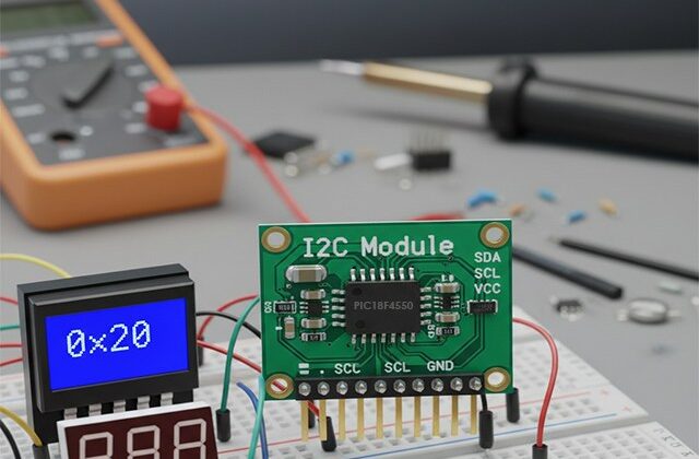
PIC18F4550 I²C Pins
The I²C module in the PIC18F4550 uses the MSSP peripheral.
- SCL → RC3 (pin 18)
- SDA → RC4 (pin 23)
You can configure the MSSP as Master or Slave depending on your application.
🔹 Step 1: Configuring I²C Master Mode
We’ll configure the I²C module to act as a Master to communicate with a slave device like an EEPROM (24C02).
Code Snippet (MPLAB X + XC8):
#include <xc.h>

#define _XTAL_FREQ 8000000

void I2C_Init(const unsigned long baud)
{
    SSPCON = 0b00101000;   // Enable MSSP in I2C Master mode
    SSPCON2 = 0x00;
    SSPADD = (_XTAL_FREQ / (4 * baud)) - 1; // Baud rate
    SSPSTAT = 0x00;
    TRISC3 = 1;  // SCL as input
    TRISC4 = 1;  // SDA as input
}

void I2C_Start(void)
{
    SEN = 1;
    while(SEN);
}

void I2C_Stop(void)
{
    PEN = 1;
    while(PEN);
}

void I2C_Write(unsigned char data)
{
    SSPBUF = data;
    while(BF);
    while(SSPSTATbits.R_nW);
}Step 2: Writing and Reading Data
You can now write bytes to an external EEPROM, RTC, or sensor using standard I²C write and read sequences.
Example:
I2C_Start();
I2C_Write(0xA0); // Slave address + Write bit
I2C_Write(0x00); // Memory address
I2C_Write(0x55); // Data
I2C_Stop();Step 3: Circuit Diagram
Connect the SCL and SDA lines between PIC18F4550 and a 24C02 EEPROM module.
- SCL (RC3) → EEPROM SCL
- SDA (RC4) → EEPROM SDA
- Pull-up resistors (4.7kΩ) to VCC (5V) on both lines.
Step 4: Testing
You can verify communication using:
- Logic analyzer (to observe start, ACK, and stop conditions)
- Reading data back using the I²C_Read function
Real-World Applications
- Interfacing EEPROM, RTC (DS1307), Temperature sensors (LM75, BMP280)
- Multi-device communication with minimal wiring
- Smart sensor networks
Learn More
🎓 Enroll in our Complete Practical Video Course on PIC18F4550 Microcontroller — includes 20+ real hardware projects, I²C, UART, ADC, PWM, and Interrupts explained hands-on!
If you enjoyed this tutorial, I2C in PIC Microcontroller and want to learn the complete practical side of PIC18F4550, including:
- Timers, Interrupts, and UART Communication
- PWM for Motor Control
- USB Interface & Sensors Integration
- Real-world Project Building
👉 Then don’t miss our Premium Course: “Mastering PIC18F4550 Microcontroller”
🎓 A complete hands-on training designed for students, hobbyists, and engineers.
Learn, Code, and Build Real Embedded Systems Projects!
➡️ Start Learning Now at Master PIC18F4550 Programming
Complete Video Course on PIC18F4550 Microcontroller
Software development tools & documents:
Tag: I2C in PIC, Inter Integrated Circuit in PIC18F4550
💬Frequently Asked Questions (FAQ)
The I²C module in the PIC18F4550 (part of the MSSP peripheral) allows the microcontroller to communicate with other I²C-compatible devices like EEPROMs, RTCs, sensors, and display modules using only two wires — SDA and SCL.
The SCL (clock) line is on RC3 (pin 18), and the SDA (data) line is on RC4 (pin 23). Both lines require external pull-up resistors, typically 4.7kΩ, connected to 5V.
Yes. The I²C module can be configured as either a Master (to control communication) or a Slave (to respond to commands from another master).
Common I²C speeds are 100 kHz (Standard Mode) and 400 kHz (Fast Mode). You can set the speed by configuring the SSPADD register in the PIC18F4550.
I²C uses open-drain (open-collector) communication. Pull-up resistors are essential to ensure proper logic HIGH levels on the SDA and SCL lines when no device is pulling them LOW.
You can verify I²C activity using a logic analyzer or oscilloscope by observing START, ACK, and STOP conditions. Alternatively, use debug UART messages in MPLAB X to confirm successful communication.
24C02 / 24LC256 – EEPROM
DS1307 / DS3231 – Real Time Clock (RTC)
BMP280 / LM75 – Temperature sensors
OLED / LCD displays
I²C requires only two lines and allows multiple devices to share the same bus. Unlike UART, it supports multiple slaves, and compared to SPI, it uses fewer pins for the same functionality.
Yes, you can configure one PIC18F4550 as a Master and another as a Slave for inter-controller communication.
You can join our Complete Practical Video Course on PIC18F4550 Microcontroller.