Interfacing Temperature Sensor LM35 with 8051 (AT89C52)
Interfacing Temperature Sensor with 8051
- Complete Video Course on AT89C52 Microcontroller
- Introduction
- Understanding LM35 Temperature Sensor
- Interfacing LM35 with ADC0804
- Connection Summary:
- Working Explanation
- Circuit Design in Proteus
- Applications
- Summary
- Learn More
- Complete Video Course on AT89C52 Microcontroller
- Downloading and Installing Keil µVision IDE
- 💬Frequently Asked Questions (FAQ)
Would you like to join our comprehensive practical video course on the AT89C52 Microcontroller?
Complete Video Course on AT89C52 Microcontroller

Introduction
Interfacing Temperature Sensor with 8051: Temperature measurement is one of the most common tasks in embedded systems. Sensors like the LM35 provide an easy way to measure temperature with excellent accuracy and linearity. However, since the AT89C52 microcontroller cannot process analog signals directly, we need an ADC (Analog-to-Digital Converter) such as the ADC0804 to convert the analog voltage output of the LM35 sensor into a digital value. In this tutorial, you’ll learn how to interface the LM35 temperature sensor with the AT89C52 microcontroller using the ADC0804, display the measured temperature on a 16×2 LCD, and simulate the setup in Proteus.
Understanding LM35 Temperature Sensor
The LM35 is a precision integrated-circuit temperature sensor whose output voltage is linearly proportional to the temperature in degrees Celsius.
Key Features:
- Output: 10 mV per °C (e.g., 250 mV = 25°C)
- Operating range: −55°C to +150°C
- Accuracy: ±0.5°C at room temperature
- Supply voltage: 4V to 30V
Output Relation
Vout=10mV×T(°C)
Example:
- 25°C → 250 mV
- 50°C → 500 mV
Interfacing LM35 with ADC0804
Since LM35 outputs an analog voltage, the ADC0804 converts it into an 8-bit digital number readable by the AT89C52.
Connection Steps:
- Connect LM35 output pin to Vin(+) of ADC0804.
- ADC0804 digital outputs (D0–D7) connect to Port 1 of AT89C52.
- Control pins:
- WR → P2.1
- RD → P2.0
- INTR → P2.2
- Vref/2 = 2.5V for 0–5V range (corresponding to 0–500°C full scale).
- Connect LCD to Port 0 and Port 3 to display temperature.
Circuit Description
Components Required:
- Potentiometer: 10kΩ (LCD contrast)
- AT89C52 microcontroller
- ADC0804 IC
- LM35 sensor
- 16×2 LCD module
- Resistors: 10kΩ (x2), 330Ω (for LCD backlight)
- Capacitor: 150pF
Interfacing Temperature Sensor with 8051
Connection Summary:
| Component | Pin | Connected To |
|---|---|---|
| LM35 | Output | ADC0804 Vin(+) |
| ADC0804 | D0–D7 | P1.0–P1.7 |
| ADC0804 | RD, WR, INTR | P2.0, P2.1, P2.2 |
| LCD | D0–D7 | Port 0 |
| LCD | RS, EN | P3.0, P3.1 |
| LCD | RW | GND |
Example Code: LM35 Interfacing with AT89C52
#include <reg51.h>
#define lcd P0
sbit rs = P3^0;
sbit en = P3^1;
sbit rd = P2^0;
sbit wr = P2^1;
sbit intr = P2^2;

void delay(unsigned int t)
{
    unsigned int i, j;
    for(i=0;i<t;i++)
        for(j=0;j<1275;j++);
}

void lcd_cmd(unsigned char c)
{
    lcd = c;
    rs = 0; en = 1; delay(2); en = 0;
}

void lcd_data(unsigned char d)
{
    lcd = d;
    rs = 1; en = 1; delay(2); en = 0;
}

void lcd_init()
{
    lcd_cmd(0x38);
    lcd_cmd(0x0C);
    lcd_cmd(0x06);
    lcd_cmd(0x01);
    lcd_cmd(0x80);
}

void lcd_string(char *s)
{
    while(*s)
        lcd_data(*s++);
}

unsigned char read_adc()
{
    unsigned char val;
    wr = 0; delay(1); wr = 1;
    while(intr == 1);
    rd = 0;
    val = P1;
    rd = 1;
    return val;
}

void main()
{
    unsigned char adc_val;
    float temp;
    unsigned char t1, t2, t3;

    lcd_init();
    lcd_string("Temp: ");

    while(1)
    {
        adc_val = read_adc();
        temp = (adc_val * 5.0 * 100) / 255;  // Convert ADC value to temperature
        t1 = ((int)temp / 100) + 48;
        t2 = (((int)temp / 10) % 10) + 48;
        t3 = ((int)temp % 10) + 48;

        lcd_cmd(0x86);
        lcd_data(t1);
        lcd_data(t2);
        lcd_data('.');
        lcd_data(t3);
        lcd_data('C');

        delay(300);
    }
}Working Explanation
- The LM35 outputs an analog voltage proportional to the temperature.
- The ADC0804 converts that voltage into an 8-bit digital value.
- The microcontroller reads the ADC output and converts it into a temperature value using the formula
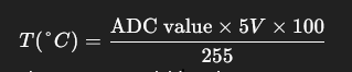
- The temperature is displayed on the LCD as a readable string.
Circuit Design in Proteus
In Proteus, place:
- AT89C52
- ADC0804
- LM35 sensor
- 16×2 LCD
- Potentiometer for LCD contrast
- RC network (10kΩ and 150pF) for ADC clock
Run the simulation and adjust the LM35’s temperature value. The LCD will display the current temperature in °C.
Applications
- Digital thermometer
- Environmental monitoring system
- Smart home temperature control
- Industrial temperature sensing
Summary
The LM35 and ADC0804 combination with the AT89C52 microcontroller is a simple yet powerful setup for temperature measurement. This project demonstrates analog sensor interfacing, digital conversion, and LCD output display — essential skills in embedded systems development.
Learn More
Do you want to go beyond just configuration and build real embedded projects?
🎓 Join our Complete Practical Video Course to Master the AT89C52 Microcontroller.
Get step-by-step guidance on Timers, Interrupts, UART, I/O Interfacing, ADC (using ADC0804), and I²C/SPI (Software Implementation) — with real circuits, simulations, and hardware demonstrations!
Complete Video Course on AT89C52 Microcontroller
Downloading and Installing Keil µVision IDE
- Visit the official Keil website at https://www.keil.com or KEIL IDE
- Navigate to the Downloads → C51 Compiler section.
- Register (if required) and download the latest version of Keil µVision for 8051 (C51).
- Run the installer and follow the on-screen instructions.
- Once installed, launch the Keil µVision IDE from the Start Menu.