PWM in PIC Microcontroller (PIC18F4550)
- Complete Video Course on PIC18F4550 Microcontroller
- Understanding and Configuring PWM in PIC Module of PIC18F4550
- What is PWM in PIC?
- Step 1: Understanding PWM in PIC18F4550
- Step 2: Registers Used for PWM Configuration
- Note: Before starting the Step 3 below, install Microchip software tools:
- Step 3: Step-by-Step Configuration (with Code)
- Step 4: PWM Frequency Calculation
- Step 5: Practical Demonstration
- Step 6: Common Applications of PWM in Projects
- Components You’ll Need for This Experiment
- Next Steps – Mastering PIC18F4550 the Practical Way
- Complete Video Course on PIC18F4550 Microcontroller
- 💬Frequently Asked Questions (FAQ)
Complete Video Course on PIC18F4550 Microcontroller

Understanding and Configuring PWM in PIC Module of PIC18F4550
PWM (Pulse Width Modulation) is one of the most powerful and widely used techniques in embedded systems. From controlling motor speed to adjusting LED brightness -PWM is everywhere! In this tutorial, you’ll learn how to configure and use the PWM in PIC microcontroller (PIC18F4550) using the CCP (Capture/Compare/PWM) feature.
Like all Bitziga tutorials, this is a hands-on, practical guide, perfect for beginners and students learning microcontrollers the engineering way.
What is PWM in PIC?
- PWM stands for Pulse Width Modulation — a method of controlling the average voltage delivered to a load by varying the ON time (duty cycle) of a digital pulse.
For example: - 0% Duty Cycle → Output always LOW
- 50% Duty Cycle → Equal ON/OFF time (average = 50%)
- 100% Duty Cycle → Output always HIGH
PWM is used in: - DC Motor speed control
- LED brightness control
- Audio tone generation
- Servo control
Step 1: Understanding PWM in PIC18F4550
PIC18F4550 supports PWM mode through its CCP (Capture/Compare/PWM) modules:
- CCP1 → output on RC2 (Pin 17)
- CCP2 → output on RC1 (Pin 16)
Each CCP module uses Timer2 as the time base for generating the PWM signal.
Step 2: Registers Used for PWM Configuration
| Register | Function |
|---|---|
| PR2 | Sets the PWM period (controls frequency) |
| CCPR1L / CCP1CON<5:4> | Sets the duty cycle (10-bit) |
| T2CON | Controls Timer2 (prescaler, enable) |
| CCP1CON | Configures CCP mode (PWM, compare, capture) |
Note: Before starting the Step 3 below, install Microchip software tools:
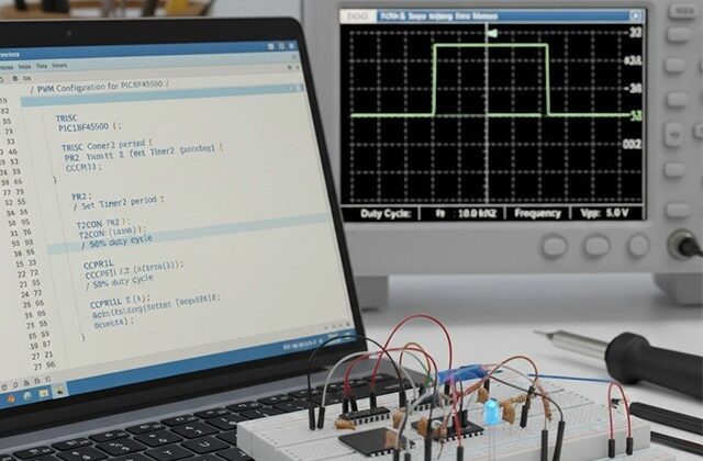
Step 3: Step-by-Step Configuration (with Code)
Let’s configure CCP1 (RC2) for a PWM output of 5 kHz frequency and 50% duty cycle.
#include <xc.h>
#define _XTAL_FREQ 8000000  // 8 MHz crystal oscillator

void PWM_Init(void)
{
    // Step 1: Set CCP1 pin (RC2) as output
    TRISC2 = 0;

    // Step 2: Set PWM period
    PR2 = 0x9B;        // PR2 = 155 -> 5 kHz PWM frequency (calculated below)

    // Step 3: Set duty cycle
    CCP1CON = 0b00001100;    // CCP1 in PWM mode
    CCPR1L = 0x4E;           // Upper 8 bits of duty (50%)
    CCP1CONbits.DC1B = 0;    // Lower 2 bits

    // Step 4: Configure Timer2
    T2CON = 0b00000100;      // Timer2 ON, prescaler = 1

    // PWM is now active on RC2
}

void main()
{
    PWM_Init();
    while(1)
    {
        // Vary duty cycle for demonstration
        for(unsigned int duty = 0; duty < 1023; duty += 50)
        {
            CCPR1L = duty >> 2;
            CCP1CONbits.DC1B = duty & 0x03;
            __delay_ms(20);
        }
    }
}
Step 4: PWM Frequency Calculation
The PWM frequency is given by:
PWM frequency = FOSC/[{(PR2) + 1} • 4  • (TMR2 Prescale Value)]
PWM period = [(PR2) + 1] • 4 • TOSC • (TMR2 Prescale Value)

For example:
FOSC = 1/TOSC = 8 MHz
Prescaler = 1
PR2 = 155

FPWM = 8,000,000/(4×156×1)=12,820Hz≈12.8kHz
Adjust PR2 and prescaler to get your desired frequency.
Step 5: Practical Demonstration
Connect an LED or a DC motor to RC2 through a transistor or driver circuit.
| Component | Connection |
|---|---|
| LED + Resistor | RC2 → LED → 330Ω → GND |
| DC Motor | RC2 → Transistor base (e.g., BC547) → Motor → +5V |
As you vary the duty cycle, the LED brightness or motor speed changes accordingly — a visual proof of PWM in action!
Step 6: Common Applications of PWM in Projects
- DC Motor Control
→ Adjust motor speed using varying duty cycles. - LED Dimming
→ Smooth brightness control for displays or indicators. - Servo Control
→ Generate precise pulse widths to position servos. - Audio Signal Generation
→ Generate tones using variable frequencies.
Components You’ll Need for This Experiment
- PIC18F4550 Development Board
- LED or DC Motor
- BC547 or L293D Motor Driver
- 330Ω resistor
- 5V regulated power supply
- MPLAB X IDE with XC8 compiler
Next Steps – Mastering PIC18F4550 the Practical Way
If you found this guide useful and want to learn every module step-by-step,
join our premium course:
“Mastering PIC18F4550 Microcontroller” – a complete hands-on training program designed for students, hobbyists, and engineers that covers:
✅ ADC, Timers, Interrupts, UART
✅ PWM, I2C, SPI, and USB modules
✅ Real-world project implementation with the hardware
Learn, Code, and Build Real Embedded Systems Projects!
➡️ Start Learning Now at Master PIC18F4550 Programming
Complete Video Course on PIC18F4550 Microcontroller